The Cortex Bridge fits a two-part printed case that sticks to the printer's rear panel with double-sided foam tape. The case leaves the USB-C, PWR IN and BUFFER connectors open, shows the three LEDs through light guides in the lid, and has a slot for a screwdriver to reach the PWR IN screws. The filament path needs two more printed parts: the PTFE tube coupler v5 on every printer, and a PTFE splitter with more than one AMS.
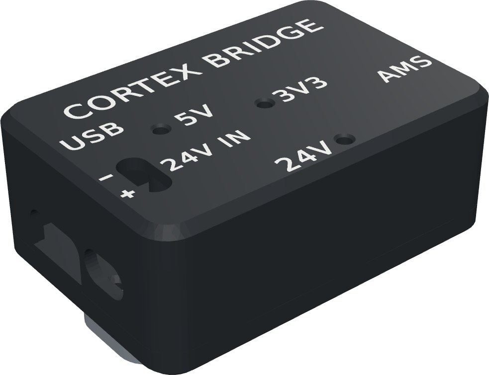
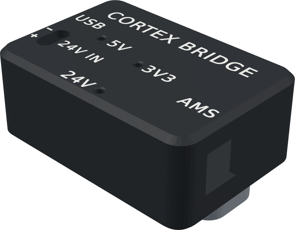
The grey part underneath is the optional DIN clip.
¶ Files to print
The case files are in the OpenAMS repository under hardware/cortex-bridge-case, with STEP versions of the same parts for CAD. They are the standard case, for boards without the optional Ethernet jack: it has no Ethernet opening and no debug-header opening.
| Part | Picture | File | Notes |
|---|---|---|---|
| Base | 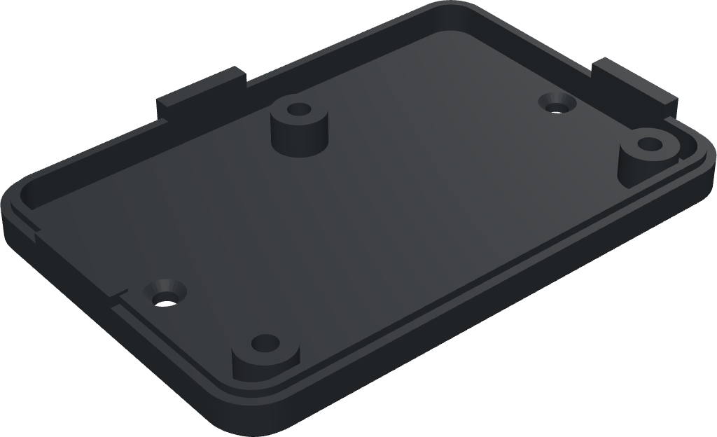 |
bridge_case_base_standard.stl | Print as oriented, no supports. |
| Lid | 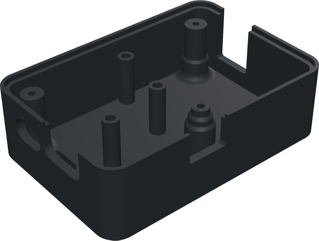 |
bridge_case_lid_standard.stl | Prints roof-down, no supports. |
| Lid with two-colour lettering (alternative) | bridge_case_lid_standard_2colour.3mf | Instead of the plain lid, on a printer with two filaments: give the lettering a contrasting colour. The lettering alone is bridge_case_lid_standard_letters.stl. | |
| DIN rail clip (optional) | 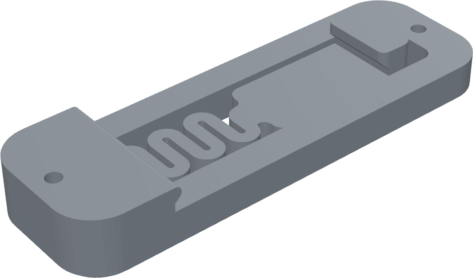 |
din_clip.stl | TS35 rail, instead of the foam tape. |
| PTFE tube coupler v5 (every printer) | 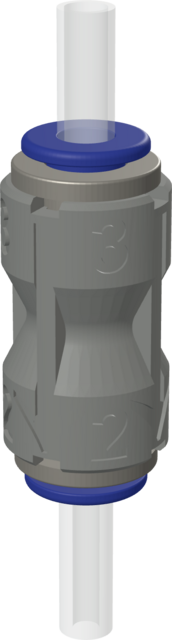 |
ptfe_coupler_v5.stl | 12 × 12 × 20 mm; takes two ECAS04 push-fit collets. See below. |
| PTFE splitter (optional) | 2 to 5 way PTFE splitter (MakerWorld) | Only with 2 to 4 AMS units. Merges their tubes into one tube to the buffer. From MakerWorld, not from the OpenAMS repository. |
Material: PETG, ASA or ABS. PLA softens behind an enclosed or heated printer.
¶ The PTFE tube coupler v5
The coupler joins the buffer's outgoing tube to the tube that runs to the toolhead, just before the printer. Fit an ECAS04 collet in each end.
- Its 3 end takes the 3 mm ID / 4 mm OD tube from the buffer.
- Its 2 end takes the tube to the toolhead: 3 mm ID, or 2 mm ID for an extruder whose entrance only takes 2 mm ID tube (the Orbiter, for example).
- Inside, it tapers smoothly from 3 mm to 2 mm. Where 3 mm tube meets 2 mm tube without it, the 1 mm step catches the filament tip.
¶ Assemble the case
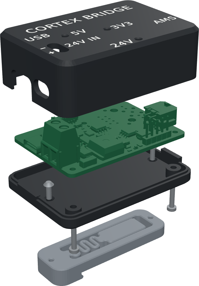
Top to bottom in the picture: the lid, the Cortex Bridge board, the base, the three M2 × 10 case screws from below, the two M2 × 6 countersunk screws for the DIN clip, and the optional DIN clip.
- Optional DIN clip. Screw it to the outside of the base first, with the two M2 × 6 countersunk screws driven from inside the base.
- Board into the base. Lay the board in the base, its three mounting holes on the base's standoffs, with USB-C and PWR IN on the same side as the base's openings.
- Lid on. Its notches go over the USB-C, BUFFER and PRGRM connectors.
- Screws from below. Turn the case over and drive the three M2 × 10 screws through the base and the board into the lid. Snug, not tight: the lid is plastic.
- LED light guides. Push a piece of 1.75 mm clear filament into each of the three LED holes in the lid until it stops on the LED, then cut it flush with the roof. The roof-to-LED depth is about 15.7 mm.
¶ Mount it
Stick double-sided foam tape to the bottom of the base (not to the DIN clip), clean the printer's rear panel, and press the case on for a few seconds. Place it within reach of the printer's 24 V supply and of the buffer cable. On a printer with a DIN rail, clip it to the rail instead, for example under the printer. If Bambu Lab's short 4-pin cable from the buffer doesn't reach that far, add a BIQU 4-pin 1 m extension (BIQU, Amazon) between it and the bridge: one 4-pin run from the buffer to the bridge.
¶ Bill of materials
| Item | Qty | Specification | Notes |
|---|---|---|---|
| Cortex Bridge board | 1 | Rev A4 | |
| Stronger buffer spring | 1 | Supplied with the bridge | Fit it in the buffer: Before you start. |
| Printed base | 1 | bridge_case_base_standard.stl |
PETG, ASA or ABS. |
| Printed lid | 1 | bridge_case_lid_standard.stl or the two-colour 3MF |
PETG, ASA or ABS. |
| Socket head cap screws | 3 | M2 × 10, hex socket, ISO 4762 / DIN 912 | M2 × 10 button heads (ISO 7380) also fit. From below, through the base and the board into the lid; they sit flush in 4.4 mm counterbores. |
| Clear filament | 3 pieces | 1.75 mm, clear (natural), about 20 mm each | LED light guides. Cut flush after fitting. |
| Double-sided foam mounting tape | 1–2 strips | Outdoor or VHB-type | For the printer's rear panel. |
| USB data cable | 1 | USB-A to USB-C | From the Klipper computer to the bridge. A data cable, not charge-only. |
| Wires for 24 V | 1 pair | At least 5 A; 0.75 mm² (18 AWG) or thicker | From spare +24 V and 0 V terminals on the printer's 24 V supply to PWR IN. The board's fuse is 5 A. |
| AMS filament buffer, with its 4-pin buffer cable | 1 | Original Bambu Lab parts | Both come with the AMS1. For an AMS 2 Pro, Bambu Lab sells the filament buffer with its cable as an addition. The cable runs from the bridge's BUFFER connector to the buffer. |
| 6-pin AMS cable | 1 per AMS | Stock Bambu Lab cable | From the buffer to the first AMS, and from each AMS to the next. |
| 4-pin cable extension (optional) | 1 | BIQU AMS Lite cable extension, 4-pin, 1 m (BIQU, Amazon) | Between Bambu Lab's 4-pin cable and the bridge, when the bridge sits further from the buffer (for example on its DIN clip under the printer). A 0.5 m version is also sold. |
| AMS unit | 1 to 4 | AMS1, AMS 2 Pro or AMS HT | Daisy-chained on their 6-pin cables: buffer → first AMS → next AMS. |
| PTFE tube | As needed | 3 mm ID / 4 mm OD up to the coupler; after it 3 mm ID, or 2 mm ID where the extruder needs it | Path: AMS → splitter → buffer → coupler → toolhead. |
| PTFE tube coupler v5, printed | 1 | ptfe_coupler_v5.stl |
Just before the printer. |
| ECAS04 push-fit collets | 2 | ECAS04 | For the coupler, one per tube. |
| Filament cutter at the toolhead | 1 | Already on the printer. | |
| PTFE splitter, printed (optional) | 1 | 2 to 5 way PTFE splitter | Only with 2 to 4 AMS units. |
| DIN clip (optional) | 1 | din_clip.stl |
TS35 rail, instead of the foam tape. |
| Countersunk screws (optional) | 2 | M2 × 6, hex socket, ISO 10642 / DIN 7991 | For the DIN clip. |
Next: Quick start, to wire the bridge and install the software.