Here follows some issues (collected from field reports), and their resolutions.
¶ #1: Klipper Unable to Connect to FPS, Lost UUID, FPS LED Power light does not come on
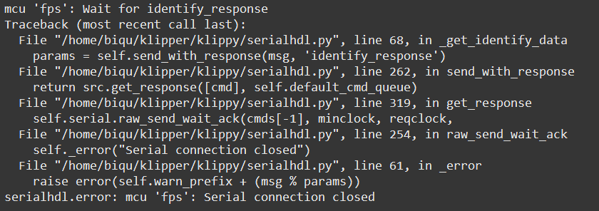
If you're encountering issues where Klipper cannot connect to the Filament Position Sensor (FPS) and the FPS UUID is lost, follow these steps to diagnose and resolve the problem.
¶ Symptoms
- Klipper fails to connect to the FPS.
- The FPS UUID is not recognized or appears lost.
- The FPS LED does not illuminate when powered.
¶ Potential Causes
- Blown fuse on the FPS board.
- Voltage spikes exceeding 27V, triggering the crowbar circuit and blowing the fuse.
- Overdrawn current via the USB OUT connector (over 1A) blowing the fuse.
¶ Diagnostic Steps
-
Power Cycle:
- Turn off all equipment.
- Wait for a few seconds.
- Turn the equipment back on and check if the FPS reconnects.
-
Check FPS LED:
- Observe if the LED on the FPS board lights up when powered.
- If the LED remains off, proceed to the next step.
-
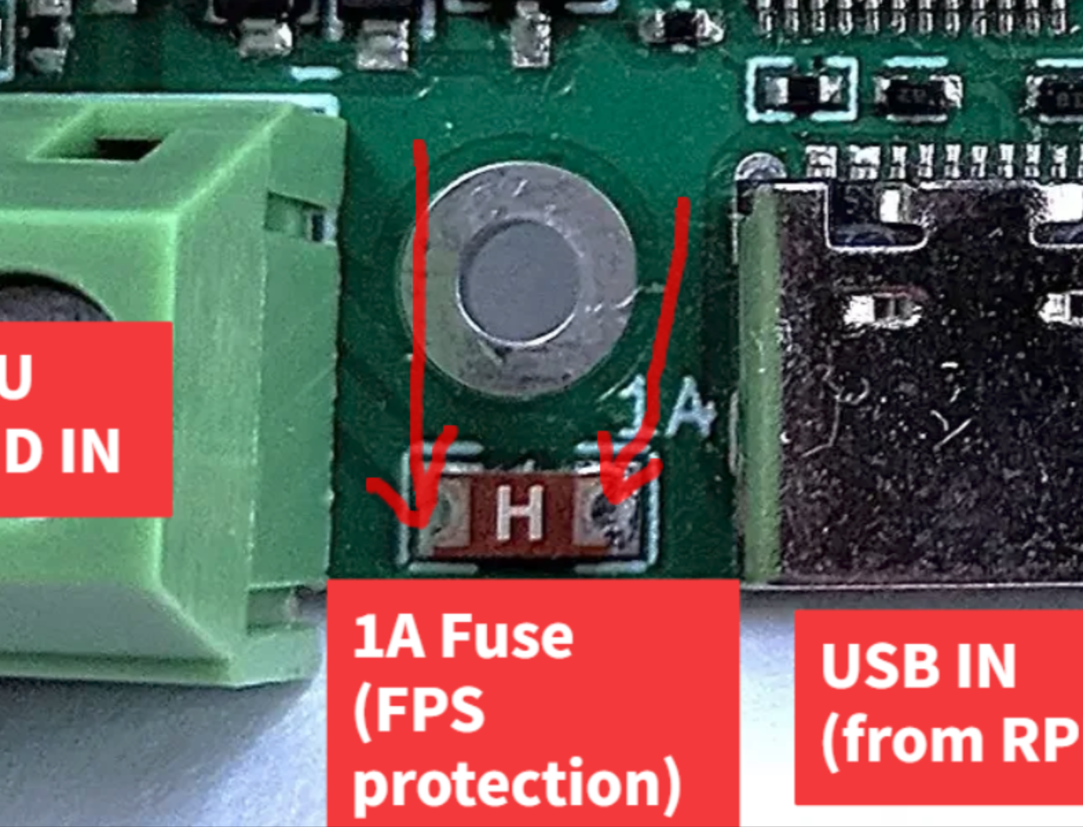
Inspect the Fuse:
- Power off the system.
- Locate the 1A fuse on the FPS board.
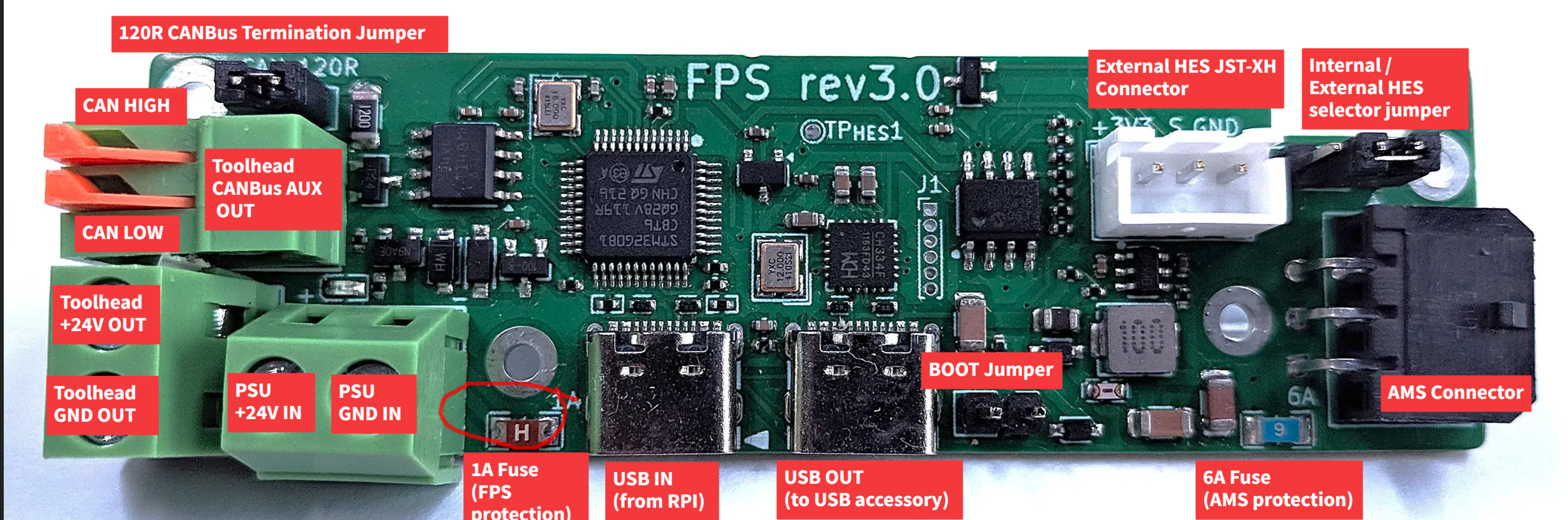
- Use a multimeter to check for continuity across the fuse.
- If there's no continuity, the fuse is blown.
-
Measure Power Supply Voltage:
- With the system powered on, measure the voltage at the power supply terminals.
- Insure the voltage is within the acceptable range (typically around 24V).
- Voltages approaching or exceeding 27V can trigger the crowbar circuit, causing the fuse to blow.
¶ Resolution
-
Replace the Blown Fuse:
- Obtain a replacement 1A fuse. The Littelfuse 0466001.NRHF is a suitable choice.
- Desolder the blown fuse and solder the new one in place.
-
Prevent Future Voltage Spikes:
- Insure your power supply is stable and does not produce voltage spikes.
- Consider using a power supply with over-voltage protection.
-
Prevent overcurrent (more than 1A)
- If you have something placed in the USB OUT port, make sure the device is not shorting, or drawing more than 500mA from the bus.
- A large draw can from the USB bus can cause the current to trip the 1A fuse.
-
Verify FPS Functionality:
- After replacing the fuse, power on the system.
- Check if the FPS LED illuminates, indicating proper power.
- Confirm that Klipper recognizes the FPS and the UUID is detected.
¶ Additional Tips
-
Using a Multimeter as a Temporary Bridge:
- If a replacement fuse is not immediately available, you can use a multimeter in current measurement mode to temporarily bridge the fuse terminals.
- Set the multimeter to measure current and connect the probes across the fuse terminals.
- This method allows you to test if the FPS powers on, but it's not a permanent solution.
- The draw by the FPS should be minimal about 5mA, if a signfinicantly larger draw takes place, check the USB OUT is in good condition and not drawing more than 500mA from the port.
- If, even without the USB OUT, being used the FPS continuous to draw significant (more than 100mA) current, it is possible the board has some other fault and needs to be replaced.
-
Understanding the Crowbar Circuit:
- The FPS board includes a crowbar circuit designed to protect it from over-voltage.
- If the input voltage exceeds approximately 27V, the circuit activates, creating a short to blow the fuse and protect the board.
- Regularly monitor your power supply to ensure it remains within the safe operating range.
¶ #2 When using katapult on the FPS, the UUID does not show on CANBUS
Currently, we are investigating an issue in which katapult does not enter the bootloader when flashed with the latest commit on katapult's git repository. The current fully working workaround, is to flash the FPS with a previous commit:
cd ~/katapult git checkout 081918ad769d1f1104ca253a4a8ace02147c345d make menuconfig make clean && make sudo dfu-util -d 0483:df11 -a 0 -R -D ~/katapult/out/katapult.bin -s0x08000000:mass-erase:force
¶ #3 The STM32 Device is Not Detected When Connecting FPS Board to Raspberry Pi (RPI)
¶ Description:
A user reported an issue where the STM32 device does not appear when the FPS board is connected to a Raspberry Pi 4 via USB. While the other USB ports on the Raspberry Pi work fine, one port is non-responsive, likely due to a physical issue or defect in that specific port. Despite this, the FPS board should always show the built-in USB hub, regardless of whether it is in DFU mode, Katapult mode, pure CANBus device mode, or CANBus bridge mode.
When running the lsusb command, the following device should always appear if the FPS is powered and connected properly:
Bus 001 Device 006: ID 1a86:8091 QinHeng Electronics USB HUB
If this device does not appear, follow these troubleshooting steps:
¶ Troubleshooting Steps:
- Check FPS LED: Ensure the LED on the FPS board is on. If the LED is off, this may indicate a blown fuse (refer to Issue #1 for more details).
- Verify USB Cable: Ensure you are not using a power-only USB cable. Some USB-C cables are designed for power delivery only and do not transmit data.
- Test with a Different Cable and USB Port:
- Use a known working USB cable and port. For testing, you can try using the cable connected to your printer’s mainboard—unplug it and re-plug it into the FPS board.
- After doing this, run
lsusbagain. You should first see the mainboard disappear from the list, and then see the QinHeng Electronics USB HUB device appear.
¶ Expected Behavior:
The FPS board, when connected to the Raspberry Pi, should always show the QinHeng Electronics USB HUB device in lsusb output.
¶ Actual Behavior:
The QinHeng Electronics USB HUB device does not show up in lsusb output, even though the FPS board is powered on and connected correctly.
¶ Workaround:
-
The issue may be caused by a malfunctioning or damaged USB port on the Raspberry Pi. To troubleshoot:
- Inspect the USB port for any visible damage or obstructions (e.g., dirt, bent pins).
- Test different cables and USB ports to ensure they are functioning properly.
- If the issue persists, the problematic USB port on the Raspberry Pi may need to be replaced, or the device may need to be replaced if still under warranty.
-
As a temporary solution, use the available working USB ports on the Raspberry Pi, or consider using a USB hub to expand connectivity.
¶ Additional Notes:
- Some USB cables are power-only and may not support data transfer. Make sure to use a data-capable cable for the connection.
- If the Raspberry Pi is new and the port remains unresponsive, consider contacting the manufacturer or retailer for a replacement.
¶ Resolution:
- If a USB port is confirmed to be faulty on the Raspberry Pi, it may need to be replaced.
- Alternatively, users can bypass the issue by using an external USB hub or the working USB ports available.
¶ #4 OpenAMS loads fine, but fails to unload, it pauses and I see a blinking red light
¶ Troubleshooting OAMS Filament Unloading Issues
If the OpenAMS (OAMS) system is unable to unload filament from the toolhead follow these troubleshooting steps to diagnose and resolve the issue.
¶ 1. Understanding the Issue
- The AMS pauses to prevent grinding the filament, which can damage the motors or PTFE tube.
- It detects this state by monitoring filament movement via an encode.
- If the filament remains stuck in the toolhead extruder, unloading will fail, and the OAMS will pause.
¶ 2. Verify Cutter Functionality
- Ensure the cutter is operational, as the toolhead extruder cannot retract filament if it has not been properly cut.
- To test:
- Unload the AMS system.
- Remove the reverse Bowden tube from the toolhead extruder.
- Cut a 300mm piece of filament and manually place it into the toolhead extruder gears.
- Heat the hotend to 240°C (if using ABS).
- Run:
G1 E100 F300to load the filament into the hotend. - Execute the
CUT_FILAMENTmacro. - Retract using:
G1 E<variable_extrusion_unload_length> F1000(replace<variable_extrusion_unload_length>with your configured value). - Check if the filament is free from the toolhead extruder after retraction.
¶ 3. Adjust Retraction Length
- If the filament remains stuck, increase
variable_extrusion_unload_lengthin the_TXmacro. - Set it to a high value (e.g.,
100mm):- This ensures the filament fully exits the toolhead extruder gears before stopping.
- Run the test again with the new value.
¶ 4. Verify AMS Rewind Function
- Reconnect the PTFE tube to the toolhead ECAS or pneumatic fitting.
- Issue the following command to load filament:
OAMS_LOAD_SPOOL OAMS=1 SPOOL=0- This should position the filament onto the extruder gears without operating the toolhead extruder.
- Issue the unload command:
OAMS_UNLOAD_SPOOL OAMS=1- If the filament rewinds normally, AMS is functioning correctly.
- If unloading fails, something in the filament path is obstructing movement.
¶ 5. Additional Considerations
- If the issue persists, inspect the filament path for obstructions.
- Verify the cutter alignment and sharpness.